| Name | Value | Units of Measurement |
|---|---|---|
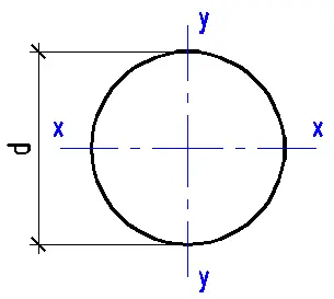
| Circle diameter | {{D1*k1_1 | fix2:x1}} |
|
| Circle area | {{A1*k1_2 | fix2:x2}} |
|
| Section modulus Wx | {{Wx1*k1_3 | fix2:x3}} |
|
| Section modulus Wy | {{Wy1*k1_4 | fix2:x4}} |
|
| Moment of inertia Ix | {{Ix1*k1_5 | fix2:x5}} |
|
| Moment of inertia Iy | {{Iy1*k1_6 | fix2:x6}} |
|
| Radius of gyration ix | {{ix1*k1_7 | fix2:x7}} |
|
| Radius of gyration iy | {{iy1*k1_8 | fix2:x8}} |
|
| Name | Value | Units of Measurement |
|---|---|---|
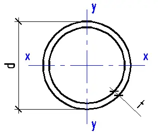
| Pipe diameter | {{D2*k2_1 | fix2:x9}} |
|
| Pipe area | {{A2*k2_2 | fix2:x10}} |
|
| Section modulus Wx | {{Wx2*k2_3 | fix2:x11}} |
|
| Section modulus Wy | {{Wy2*k2_4 | fix2:x12}} |
|
| Moment of inertia Ix | {{Ix2*k2_5 | fix2:x13}} |
|
| Moment of inertia Iy | {{Iy2*k2_6 | fix2:x14}} |
|
| Radius of gyration ix | {{ix2*k2_7 | fix2:x15}} |
|
| Radius of gyration iy | {{iy2*k2_8 | fix2:x16}} |
|
| Name | Value | Units of Measurement |
|---|---|---|
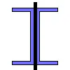
| I-beam area | {{A3*k3_2 | fix2:x17 }} |
|
| Section modulus Wx | {{ Wx3 *k3_3 | fix2:x18 }} |
|
| Section modulus Wy | {{ Wy3*k3_4 | fix2:x19 }} |
|
| Moment of inertia Ix | {{ Ix3 *k3_5 | fix2:x20 }} |
|
| Moment of inertia Iy | {{ Iy3*k3_6 | fix2:x21 }} |
|
| Radius of gyration ix | {{ ix3*k3_7 | fix2:x22 }} |
|
| Radius of gyration iy | {{ iy3*k3_8 | fix2:x23 }} |
|

| Name | Value | Units of Measurement |
|---|---|---|
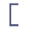
| Channel area | {{ A4*k4_2 | fix2:x24 }} |
|
| Section modulus Wx | {{ Wx4*k4_3 | fix2:x25 }} |
|
| Section modulus Wy | {{ Wy4*k4_4 | fix2:x26 }} |
|
| Moment of inertia Ix | {{ Ix4*k4_5 | fix2:x27 }} |
|
| Moment of inertia Iy | {{ Iy4*k4_6 | fix2:x28 }} |
|
| Radius of gyration ix | {{ ix4*k4_7 | fix2:x29 }} |
|
| Radius of gyration iy | {{ iy4*k4_8 | fix2:x30 }} |
|
| Name | Value | Units of Measurement |
|---|---|---|
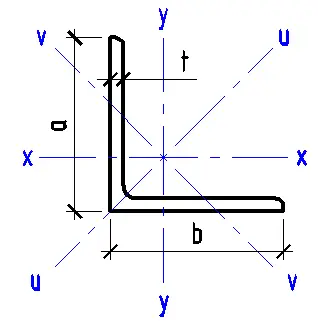
| Angle area | {{ A5*k5_2 | fix2:x31 }} |
|
| Section modulus Wx | {{ Wx5*k5_3 | fix2:x32 }} |
|
| Section modulus Wy | {{ Wy5*k5_4 | fix2:x33 }} |
|
| Section modulus Wuv | {{ Wuv5*k5_5 | fix2:x34 }} |
|
| Moment of inertia Ix | {{ Ix5*k5_6 | fix2:x35 }} |
|
| Moment of inertia Iy | {{ Iy5*k5_7 | fix2:x36 }} |
|
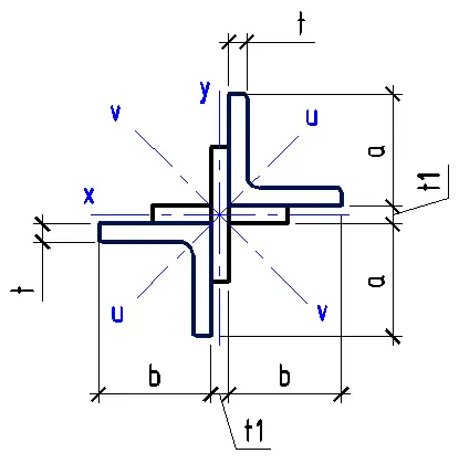
| Moment of inertia Iuv (min) | {{ Iuv5*k5_8 | fix2:x37 }} |
|
| Radius of gyration ix | {{ ix5*k5_9 | fix2:x38 }} |
|
| Radius of gyration iy | {{ iy5*k5_10 | fix2:x39 }} |
|
| Radius of gyration iuv (min) | {{ iuv5*k5_11 | fix2:x40 }} |
|
| Name | Value | Units of Measurement |
|---|---|---|
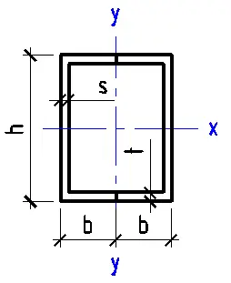
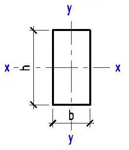
| Rectangle area | {{ A6*k6_2 | fix2:x41 }} |
|
| Section modulus Wx | {{ Wx6*k6_3 | fix2:x42 }} |
|
| Section modulus Wy | {{ Wy6*k6_4 | fix2:x43 }} |
|
| Moment of inertia Ix | {{ Ix6*k6_5 | fix2:x44 }} |
|
| Moment of inertia Iy | {{ Iy6*k6_6 | fix2:x45 }} |
|
| Radius of gyration ix | {{ ix6*k6_7 | fix2:x46 }} |
|
| Radius of gyration iy | {{ iy6*k6_8 | fix2:x47 }} |
|
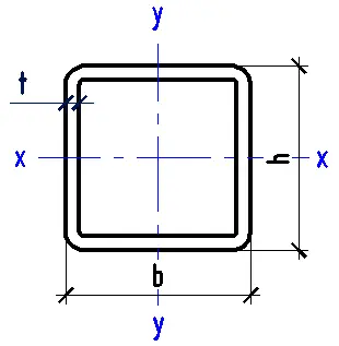
| Name | Value | Units of Measurement |
|---|---|---|
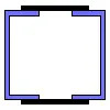
| Pipe area | {{ A7*k7_2 | fix2:x48 }} |
|
| Section modulus Wx | {{ Wx7*k7_3 | fix2:x49 }} |
|
| Section modulus Wy | {{ Wy7*k7_4 | fix2:x50 }} |
|
| Moment of inertia Ix | {{ Ix7*k7_5 | fix2:x51 }} |
|
| Moment of inertia Iy | {{ Iy7*k7_6 | fix2:x52 }} |
|
| Radius of gyration ix | {{ ix7*k7_7 | fix2:x53 }} |
|
| Radius of gyration iy | {{ iy7*k7_8 | fix2:x54 }} |
|
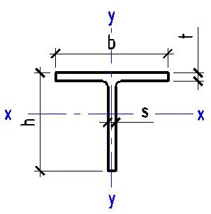
| Name | Value | Units of Measurement |
|---|---|---|
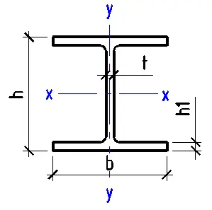
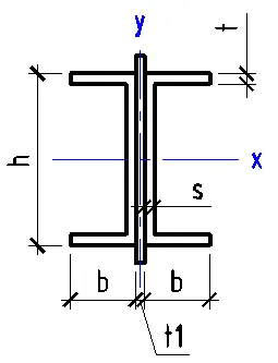
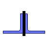
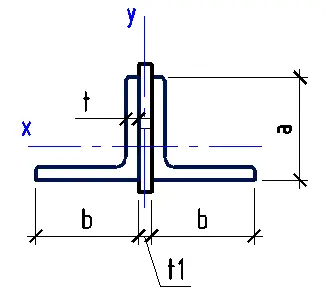
| T-beam area | {{ A8*k8_2 | fix2:x55 }} |
|
| Section modulus Wx (top) | {{ Wx8*k8_3 | fix2:x56 }} |
|
| Section modulus Wx (bottom) | {{ Wx8_1*k8_9 | fix2:x62 }} |
|
| Section modulus Wy | {{ Wy8*k8_4 | fix2:x57 }} |
|
| Moment of inertia Ix | {{ Ix8*k8_5 | fix2:x58 }} |
|
| Moment of inertia Iy | {{ Iy8*k8_6 | fix2:x59 }} |
|
| Radius of gyration ix | {{ ix8*k8_7 | fix2:x60 }} |
|
| Radius of gyration iy | {{ iy8*k8_8 | fix2:x61 }} |
|


About Moment of Inertia Calculation
The calculator determines the moment of inertia and other geometric properties of a cross-section: area A, second moments of area I, section moduli W, and radii of gyration i. These values are used for strength and deflection checks of beams, columns, and similar members, and for selecting or comparing section shapes.
The calculation is performed for typical section shapes defined by linear dimensions. The results refer to axes passing through the centroid of the section unless stated otherwise.
Guidelines and recommendations
What is calculated and in which units
Section area A is computed from the linear dimensions and represents the amount of material in the cross-section. Units: mm2 (or equivalent when converted).
Second moments of area Ix and Iy describe how the area is distributed about the x and y axes and are used in deflection and buckling calculations. Units: mm4.
Section moduli Wx and Wy are used to relate bending moment to the maximum bending stress. Units: mm3.
Radii of gyration ix and iy are used in stability checks of members (for example, slenderness). Units: mm.
Core relations used in the calculation
From second moment of area to radius of gyration the calculator uses the definition of radius of gyration.
ix = √( Ix / A ), iy = √( Iy / A )
Section modulus is computed as the ratio of second moment of area to the distance from the neutral axis to the most distant fibre.
Wx = Ix / ymax, Wy = Iy / xmax
Here ymax and xmax are the maximum distances from the axis to the extreme points of the section in the corresponding direction. For symmetric shapes this is typically half the height or width. For non-symmetric shapes the distances to the top and bottom edges may differ, and the corresponding extreme distances are used.
How second moments of area are computed for built-up sections
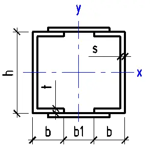
Built-up section (for example, an I-section, channel, angle, or hollow section) is represented as a sum and difference of simple shapes. For each part the calculator first finds its area Ak, the location of its centroid, and its own second moments of area about axes through that part’s centroid.
Transfer to the common axes is done using the parallel axis theorem.
Ix = Σ( Ix,k + Ak·Δyk2 ), Iy = Σ( Iy,k + Ak·Δxk2 )
Here Δxk and Δyk are the offsets of the part centroid relative to the overall section centroid. Holes and cut-outs are treated as “negative” parts, meaning their areas and moments are subtracted.
Typical formulas for basic shapes
Rectangle (width b, height h) is calculated using standard expressions about centroidal axes.
A = b·h, Ix = b·h3/12, Iy = h·b3/12
Circle (diameter d) is calculated using standard expressions about any diameter through the centre.
A = π·d2/4, Ix = Iy = π·d4/64
Circular hollow section (outer diameter D, wall thickness t) is calculated as the difference of two circles. The inner diameter d is taken as d = D − 2t (provided that D > 2t).
A = π·(D2 − d2)/4, Ix = Iy = π·(D4 − d4)/64
How the final value is chosen when there are multiple axes and extreme distances
Separate axes are evaluated separately: Ix, Wx, ix relate to bending and stability about the x axis, and Iy, Wy, iy relate to the y axis.
Minimum values may be shown as the “worst-case” for stability, especially for non-symmetric sections. A common practice is to use imin = min(ix, iy) and Imin = min(Ix, Iy).
Practical guidance for using the results
Bending and stress are commonly assessed using the section modulus. For the same bending moment, a larger W gives lower bending stress.
Deflection is sensitive to the second moment of area. For the same material and span conditions, deflection is inversely proportional to I. Increasing the section depth usually increases Ix much more than increasing the width.
Stability of members is often linked to radius of gyration and slenderness. A common relation uses the ratio L/i, where a smaller i gives a more critical case.
EU standards reference
EN 1993-1-1 (Eurocode 3) uses geometric properties (area, second moments of area, radii of gyration, section moduli) in the design of steel members.
EN 1995-1-1 (Eurocode 5) uses the same properties for timber members in strength and serviceability checks.
EN 1999-1-1 (Eurocode 9) similarly uses section properties for aluminium structures.
In these documents the geometry formulas are generally treated as standard background, and the calculated properties are then used in material strength and stability checks.
FAQs
What is the difference between second moment of area and section modulus
Second moment of area I describes how the area is distributed and directly affects stiffness and deflection. Section modulus W also accounts for the distance to the extreme fibres, so it is convenient for estimating bending stress. For a non-symmetric section, W can differ for different sides.
Why does one section have different values about the x and y axes
A section can be stiff in one direction and flexible in the other. For example, a tall narrow shape usually has a large Ix and a small Iy. That is why bending and buckling checks are done separately for each axis.
How are voids in a hollow section or holes in a section handled
A void is handled by subtracting the inner shape from the outer one. The inner area and second moments of area are taken with a negative sign because there is no material there. For a circular hollow section, the condition D > 2t must be satisfied.
Can different section shapes be compared using area only
Area indicates mass for the same material density, but it does not represent stiffness or bending resistance. Two sections with the same area can have very different I and W. For beams in bending it is common to compare both W for stress and I for deflection.
Which results are most often used for column stability
It is common to look at the radii of gyration and take the minimum i, since it produces the most critical slenderness. This is especially important for built-up and non-symmetric sections. The design check then accounts for effective length, end restraints, and the relevant Eurocode rules.