



About Wind Load Calculation
This wind load calculator determines design wind pressure on roofs, fences, and building structures. The calculation is performed by zones for a rectangular building, a duo-pitch roof, and a solid wall or fence with return corners, taking into account basic wind velocity, terrain category, structure height, object geometry, external pressure coefficients, and, where applicable, internal pressure.
For each zone, the results include the exposure factor, the resulting aerodynamic coefficient, and the design wind pressure in kN/m² and kgf/m². The pressure sign is retained: a positive value represents pressure acting toward the surface, while a negative value represents suction.
Guidelines and recommendations
Standards and calculation sequence
Standards. Wind action coefficients and the rules for dividing surfaces into zones are based on EN 1991-1-4 “Eurocode 1: Actions on structures - Part 1-4: General actions - Wind actions”. The partial factor used to obtain the design value is based on EN 1990 “Eurocode - Basis of structural design”.
Calculation sequence. First, the basic wind pressure is calculated from the basic wind velocity. The peak velocity pressure is then determined from the terrain category and reference height. After that, the building, roof, or wall is divided into zones, an aerodynamic coefficient is assigned to each zone, internal pressure is included where selected, and the partial factor is applied.
Basic wind velocity. The calculation uses the basic wind velocity vb in m/s. It must already include the directional and seasonal factors according to vb = cdir · cseason · vb,0. The values of cdir, cseason, and the fundamental basic wind velocity vb,0 are determined from the National Annex to EN 1991-1-4.
Basic wind pressure. The air density used in the calculation is ρ = 1.25 kg/m³. The basic velocity pressure is calculated from the square of the wind velocity:
qb = 0.5 · ρ · vb2 / 1000
With velocity in m/s, this formula gives qb in kN/m². Therefore, for example, doubling the wind velocity increases the pressure by a factor of four.
Terrain category and height effect
Terrain roughness. The following roughness lengths z0 and minimum reference heights zmin are used for the five terrain categories:
- Category 0:
z0 = 0.003 m,zmin = 1 m. - Category I:
z0 = 0.01 m,zmin = 1 m. - Category II:
z0 = 0.05 m,zmin = 2 m. - Category III:
z0 = 0.3 m,zmin = 5 m. - Category IV:
z0 = 1.0 m,zmin = 10 m.
Reference height. Geometric dimensions are entered in mm, while the height used for the wind profile is converted to metres. If the reference height is below zmin for the selected terrain category, zmin is used. The upper reference height limit is 200 m.
Roughness factor. The terrain factor kr is calculated first, followed by the roughness factor cr(z) and turbulence intensity Iv(z):
kr = 0.19 · (z0 / 0.05)0.07
cr(z) = kr · ln(z / z0)
Iv(z) = 1 / ln(z / z0)
The calculation assumes an orography factor of c0 = 1.0 and a turbulence factor of kI = 1.0.
Exposure factor. The k column shows the ratio of the peak velocity pressure at the selected height to the basic velocity pressure:
k(z) = (1 + 7 · Iv(z)) · cr2(z)
qp(z) = qb · k(z)
Thus, for the same basic wind velocity, the resulting pressure changes with height and terrain category.
Rectangular building
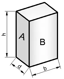
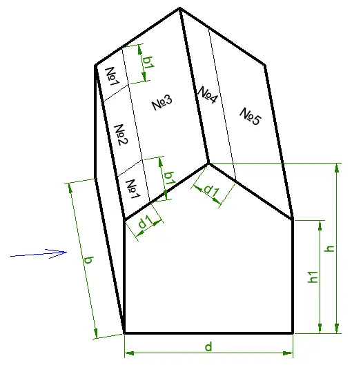
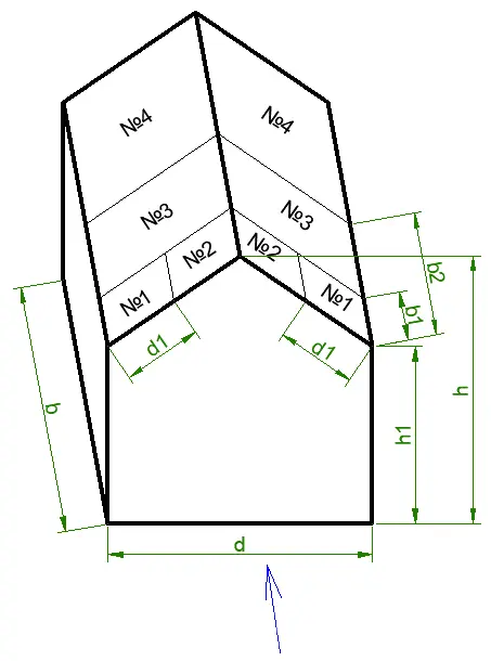
Wind direction. For wind acting on wall A, d is treated as the crosswind dimension and b as the building depth in the wind direction. For wind acting on wall B, these dimensions are interchanged. This affects both the zone dimensions and the coefficients for the windward and leeward walls.
Edge-zone width. For the side walls, the dimension e is first calculated as the smaller of the crosswind dimension and twice the building height:
e = min(crosswind dimension; 2h)
The first edge zone extends to e/5, the second to e, and the remaining part belongs to the next zone. If the building ends before a zone boundary is reached, that zone is not included in the results.
External coefficients for side walls. The calculator uses cpe,10 values of -1.2, -0.8, and -0.5 for zones A, B, and C respectively. These are cpe,10 coefficients applicable to loaded areas of approximately 10 m² or more.
Windward wall D. The coefficient depends on the ratio of height h to building depth. For h/depth ≤ 0.25, cpe,10 = +0.7 is used; for h/depth ≥ 1, +0.8 is used. Linear interpolation is applied between these values.
Leeward wall E. For h/depth ≤ 0.25, cpe,10 = -0.3 is used; at a ratio of 1, the value is -0.5; and for h/depth ≥ 5, the value is -0.7. Intermediate coefficients are obtained by linear interpolation.
Reference heights for the windward wall. If h ≤ crosswind dimension, the entire wall uses ze = h. If crosswind dimension < h ≤ 2 · crosswind dimension, the lower part uses a reference height equal to the crosswind dimension, while the upper part uses h. If h > 2 · crosswind dimension, three levels are used: the crosswind dimension, h - crosswind dimension, and h. For the side and leeward zones, peak velocity pressure is calculated at height h.
Duo-pitch roof
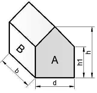
Roof pitch. The roof angle is calculated automatically from the total height h, eaves height h1, and building width d:
α = arctan((h - h1) / (d / 2))
The calculation is performed for positive roof pitches from 5° to 75°. For intermediate angles, coefficients are obtained by linear interpolation between the nearest tabulated values of the same sign.
Wind parallel to the ridge. For wind acting on wall A, the θ = 90° case is used. The result rows correspond to zones F, G, H, and I. The cpe,10 values for angles 5°, 15°, 30°, 45°, 60°, 75° are: F — -1.6, -1.3, -1.1, -1.1, -1.1, -1.1; G — -1.3, -1.3, -1.4, -1.4, -1.2, -1.2; H — -0.7, -0.6, -0.8, -0.9, -0.8, -0.8; I — -0.6, -0.5, -0.5, -0.5, -0.5, -0.5.
Wind perpendicular to the ridge. For wind acting on wall B, the θ = 0° case is used. The rows correspond to zones F, G, H, J, and I. For roof pitches where EN 1991-1-4 provides two possible pressure branches, the calculator checks both and determines the most unfavorable value separately for each zone.
5°: F-1.7 / 0.0, G-1.2 / 0.0, H-0.6 / 0.0, I-0.6, J-0.6 / +0.2.15°: F-0.9 / +0.2, G-0.8 / +0.2, H-0.3 / +0.2, I-0.4 / 0.0, J-1.0 / 0.0.30°: F-0.5 / +0.7, G-0.5 / +0.7, H-0.2 / +0.4, I-0.4 / 0.0, J-0.5 / 0.0.45°: F0.0 / +0.7, G0.0 / +0.7, H0.0 / +0.6, I-0.2 / 0.0, J-0.3 / 0.0.60°: F+0.7, G+0.7, H+0.7, I-0.2, J-0.3.75°: F+0.8, G+0.8, H+0.8, I-0.2, J-0.3.
Roof-zone geometry. For wind parallel to the ridge, e = min(d; 2h) is used, with characteristic zone boundaries at e/10, e/2, and e/4. For wind perpendicular to the ridge, e = min(b; 2h) is used, with the main boundaries at e/10 and e/4. If the roof ends before the next boundary is reached, the absent zone is not included in the results.
Roof reference height. For all duo-pitch roof zones, the peak velocity pressure qp(h) at the full building height is used.
Internal pressure
Internal pressure coefficient. If internal pressure is not included, cpi = 0 is used. When the EN internal-pressure option is selected, two values are checked: cpi = +0.2 and cpi = -0.3. For each zone, the combination producing the greatest absolute resulting pressure is selected.
Combined pressure effect. For the roof, external and internal pressures are referenced to height h, so the resulting characteristic pressure is determined from the difference between the coefficients:
wk = qp(h) · (cpe - cpi)
For building walls, external pressure may be calculated at its own reference height ze, while internal pressure is based on qp(h). The external and internal components are therefore calculated separately and then combined to obtain the most unfavorable difference. In this case, the displayed coefficient c is an equivalent resulting coefficient corresponding to the calculated pressure.
Solid wall or fence with return corners
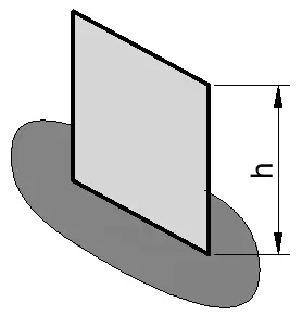
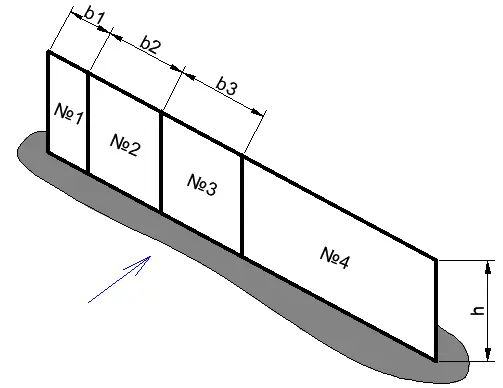
Calculation model. The calculation represents a solid free-standing wall with a solidity ratio of φ = 1 and return corners at least h long. For this configuration, the recommended net pressure coefficients cp,net from EN 1991-1-4 are used.
Zone coefficients. The successive zones use coefficients of 2.1, 1.8, 1.4, and 1.2. The zone boundaries are located at distances of 0.3h, 2h, and 4h from the wall edge.
Pressure calculation. Peak velocity pressure qp(h) at the wall height is used for all zones. Internal pressure is not applied to a free-standing wall because the calculation uses the net pressure coefficient cp,net.
Conversion to design wind pressure
Partial factor. After the characteristic wind pressure is determined, the calculator multiplies it by γQ = 1.5. This is the recommended value for an unfavorable leading variable action under EN 1990; the National Annex may specify different values for a particular design situation.
wd = γQ · wk
Result units. The main result is given in kN/m². It is also converted to kgf/m² using 1 kN/m² = 101.97 kgf/m².
National Annexes. The calculator uses the recommended coefficients from EN 1991-1-4 and γQ = 1.5. For structural design, the regional wind velocity, directional and seasonal factors, and any nationally determined coefficients should be taken from the National Annex applicable in the country where the structure is located.
FAQs
Why does wind pressure differ between zones of the same building?
Airflow interacts differently with central surface areas, edges, and corners. Stronger local suction occurs in edge zones, so their external pressure coefficients differ. The result can also vary because different zones may use different reference heights.
How should the terrain category be selected?
The terrain category is selected according to the characteristics of the ground and obstacles on the upwind side. Open terrain with few obstacles commonly corresponds to category II, suburban areas and forests to category III, and dense urban development to category IV. The relevant upwind terrain may also change when the wind direction changes.
Why can the calculated wind pressure be negative?
A negative sign represents suction: the external pressure acts away from the surface relative to the adopted positive direction. This is common on side walls, leeward surfaces, and many roof zones. Both the magnitude and the direction of the wind load are relevant when checking a structure.
Why are two internal pressure values checked?
Internal pressure can either increase external pressure or increase suction. Therefore, when the EN option is selected, the calculator checks both cpi = +0.2 and cpi = -0.3 and retains the most unfavorable combination for each zone. This accounts for both possible directions of internal pressure in a single calculation procedure.
Where should the basic wind velocity for the calculation be obtained?
Regional wind values are specified in the National Annex to EN 1991-1-4 for the country where the structure is located. The calculator uses vb, meaning the velocity after applying the directional factor cdir and seasonal factor cseason. Because wind pressure depends on the square of velocity, even a relatively small change in vb can noticeably affect the calculated wind load.