


About Pipe Flow to Velocity Calculation
This pipe flow to velocity calculator computes the average flow velocity of water, air, or gas in a pipe or duct from the given volumetric flow rate and internal cross section. The calculation is used for a quick check of operating conditions and a preliminary choice of diameter or duct size. The result is suitable for an initial estimate before a full hydraulic or aerodynamic network calculation.
Guidelines and recommendations
Calculation model and assumptions
Average velocity is assumed uniform across the section. Velocity profile, wall roughness, local resistances, and pressure losses are not included in this calculation.
Volumetric flow rate is treated as the flow rate you enter in the selected units. For air and gas, it is the volumetric flow rate at the conditions under which you specify it. Compressibility and density change along the length are not considered.
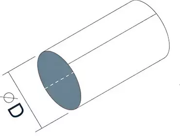
Geometry uses internal dimensions. For a circular section, the internal diameter D in mm is used. For a rectangular section, the internal dimensions A and B in mm are used.
Step 1. Flow area
Circular section is computed from the internal diameter D, mm. Conversion from mm2 to m2 is done by dividing by 1,000,000.
S = (π · D² / 4) / 1 000 000
Rectangular section is computed from the internal dimensions A and B, mm. Conversion from mm2 to m2 is done by dividing by 1,000,000.
S = (A · B) / 1 000 000
Units: S is in m2 when the sizes are given in mm.
Step 2. Converting the flow rate to m³/s
Unit conversion is done by multiplying the entered flow rate q by the conversion factor k to m3/s for the selected unit.
Q = q · k
- m³/h: k = 0.0002777778 (1/3600).
- L/s: k = 0.001 (1 L = 0.001 m³).
- L/min: k = 0.0000166667 (0.001/60).
- m³/s: k = 1.
- m³/min: k = 0.0166667 (1/60).
Step 3. Flow velocity
Main formula links volumetric flow rate and area. The velocity v is in m/s.
v = Q / S
Rounding is performed to 0.01 m/s.
How to interpret the result
For water common guidelines are about 0.3-1.0 m/s for quieter systems and 0.6-2.0 m/s where higher pressure losses are acceptable. If velocity is too high, noise and pressure losses usually increase. If velocity is too low, self-cleaning can worsen and it may be harder to achieve the required circulation.
For air in ventilation, common guidelines are 2-5 m/s for branches to rooms and 4-8 m/s for main ducts. At higher velocities, noise usually increases and acoustic requirements become stricter. For an accurate check, pressure losses are additionally calculated and acceptable noise levels are verified.
For gases typical values depend on pressure, allowable losses, and safety requirements. This calculation is useful as a first check, but design usually requires pressure loss calculation and verification of equipment operating conditions.
Related European standards and documents
- EN 806 “Specifications for installations inside buildings conveying water for human consumption”.
- EN 16798 “Energy performance of buildings. Ventilation for buildings”.
- EN 12599 “Ventilation for buildings. Test procedures and measuring methods for handing over installed ventilation and air conditioning systems”.
- EN 13480 “Metallic industrial piping”.
- ISO 5167-1 “Measurement of fluid flow by means of pressure differential devices inserted in circular cross-section conduits running full”.
FAQs
Why is velocity calculated as v = Q / S?
Volumetric flow rate Q shows how much volume passes in 1 second. Area S shows the section through which the flow passes. Dividing gives the average flow velocity in m/s.
What is the difference between average velocity and the velocity at the center?
In a real flow, velocity is not uniform across the section. It is usually higher in the center and lower near the walls. The calculator provides the average velocity, which is suitable for a preliminary estimate and an initial size selection.
In a round pipe, what affects velocity more, flow rate or diameter?
Velocity is directly proportional to flow rate. For a circular section, area is proportional to D², so a small increase in diameter noticeably reduces velocity at the same flow rate.
Why can velocity differ in a rectangular duct at the same flow rate?
Velocity depends only on cross-sectional area. Different A×B combinations give different area S. Therefore, at the same flow rate Q, velocity changes.
Can velocity alone confirm that the size is selected correctly?
Velocity provides a quick guideline, but final selection is usually verified by pressure losses and noise level. For ventilation systems and pipelines, friction losses and local resistances are often additionally calculated.