
| Position | Material | Cross-Section | Quantity | Length | Notes |
|---|---|---|---|---|---|
| prop | |||||
| main beam | - | ||||
| secondary beam | - | ||||
| flooring | - |


About Slab Formwork Calculation
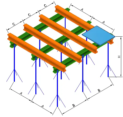
This slab formwork calculator checks the performance of formwork elements for a cast-in-place concrete floor slab. It covers the sheathing (decking), secondary beams, primary beams, and props. For each element it checks strength and deflection. For the prop it also evaluates stability. It can also provide an approximate quantity of the main formwork components for a room with the specified dimensions.
Reference values and recommendations
Regulatory basis (Eurocodes and EU standards). The calculation logic follows common European principles for actions, cross-section checks, and stability verification. As references for terminology and design approach, the following are applicable: EN 1990 “Eurocode. Basis of structural design”, EN 1991-1-1 “Eurocode 1. Actions on structures. Densities, self-weight, imposed loads for buildings”, EN 1993-1-1 “Eurocode 3. Design of steel structures. General rules and rules for buildings”, EN 1995-1-1 “Eurocode 5. Design of timber structures. General. Common rules and rules for buildings”. For temporary supporting structures and formwork, the following are often used: EN 12812 “Falsework. Performance requirements and general design”, EN 1065 “Adjustable telescopic steel props. Product specification”.
Design surface load. First, the load per 1 m2 of slab is determined as the self-weight of fresh concrete with a safety margin plus an allowance for formwork and construction actions. Adopted values are: concrete density 2500 kg/m3, safety factor 1.2, allowance 50 kg/m2.
q = 2500 · (t/1000) · 1.2 + 50
Where q is the load in kg/m2. t is the slab thickness in mm. For the force-based checks, the conversion uses gravitational acceleration g = 9.81 m/s2.
Load transfer from the slab to the formwork elements. The load is transferred sequentially from the sheathing to secondary beams, then to primary beams, and further to props. The following spacings in mm are used: C is the secondary beam spacing and also the sheathing span. A is the primary beam spacing. B is the prop spacing along the primary beam.
qline = q · (s/1000) · 9.81 / 1000
Where qline is the line load in kN/m. s is the tributary width collected by the element. For a secondary beam, s = C is typically used. For a primary beam, s = A is used. For a prop, the load is determined through the tributary area A × B.
Beam model for sheathing and beams. The sheathing and beams are treated as single-span members on pinned supports under a uniformly distributed load. The peak internal forces are determined using approximate expressions with a built-in margin.
Mmax = qline · L2 / 9.5
Qmax = 1.1 · qline · L
Where L is the span of the considered member in mm. For the sheathing, L = C. For a secondary beam, L = A is typically used. For a primary beam, L = B.
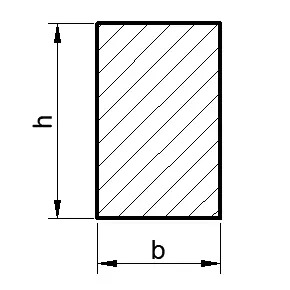
Bending strength check. For the selected cross-section, the section modulus W in mm3 is calculated. The bending stress is determined as follows.
σ = Mmax / W
The meaning of the check is that σ must not exceed the allowable material stress σallow in MPa.
Shear and equivalent stress check. For steel elements and sheet-type decking, the shear stress from the shear force and the equivalent stress from combined bending and shear can also be evaluated.
τ = Qmax · S / (t · I)
σeq = √(σ2 + 4 · τ2)
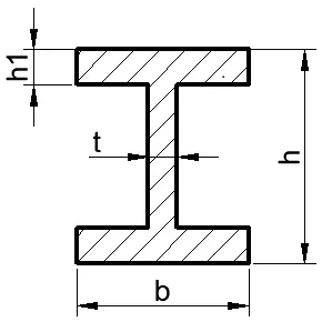
Where I is the second moment of area in mm4. S is the first moment of area of the relevant part in mm3. t is the web or sheet thickness in mm. The meaning of the check is that τ and σeq must not exceed their corresponding allowable values.
Adopted material properties. The following reference values are used in the calculations (MPa).
- Timber. The allowable bending stress is defined for strength classes C16, C24, C30 and already includes reduction factors
0.66 · 0.9 · 0.8 · 0.9: C16 → 6.84, C24 → 10.26, C30 → 12.83. The allowable shear stress is taken asτallow = 3.5. The modulus of elasticity is taken asE = 10000. - Steel. The allowable stress is taken as
σallow = (fy/1.05) · 0.9, wherefyis the yield strength. The adoptedfy/1.05values are: S235 → 223.81, S275 → 261.90, S355 → 338.10, S420 → 400. For shear,τallow = σallow · 0.58. For equivalent stress, the limitσeq,allow = σallow · 0.87is used. The modulus of elasticity is taken asE = 206000.
Deflection check. Deflection is calculated using the elastic formula for a uniformly distributed load. The expression includes an additional division by 2 as a built-in margin for system behaviour and load distribution.
f = (5/384) · qline · L4 / (E · I) / 2
Where f is the deflection in mm. The stiffness criterion is taken as f ≤ L/250. The span L is taken for the specific element. For the sheathing this is C. For the secondary beam this is A. For the primary beam this is B.
Load on a prop. The axial force in a prop is determined from the tributary area assigned to one prop. The area is taken as a rectangle A × B.
N = q · (A/1000) · (B/1000) · 9.81
Where N is the axial force in N. The effective prop length is based on the room height with deductions for the sheathing thickness and beam depths, to obtain the length of the compression member between supports.
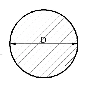
Prop slenderness. Slenderness is determined using the minimum radius of gyration i of the selected cross-section in mm.
λ = Leff / i
Where Leff is the effective prop length in mm. The following practical limits are used: for timber λ ≤ 120, for steel λ ≤ 150. Exceeding the limit indicates a high buckling risk and the need to change the system or the cross-section.
Steel prop stability. For a steel prop, a stability factor φ is used to reduce the allowable axial capacity as slenderness increases. First, the reduced slenderness is calculated.
λ̄ = λ · √(σallow/206000)
Then an upper bound is introduced for the stability factor.
φmax = 7.6 / λ̄2
The final φ value is chosen as the more conservative one in terms of safety margin. The utilization check is performed as follows.
η = N / (A · σallow · φ)
The condition is η ≤ 1. Here A is the prop cross-sectional area in mm2.
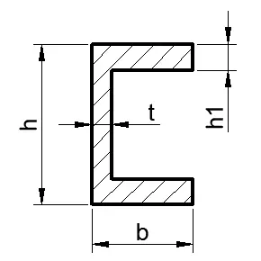
Local buckling of thin elements (when applicable). For some steel profiles, the thinness of the web and flange is assessed through width-to-thickness ratios with consideration of the stress level. The typical form of the used parameters is as follows.
yw = (hw/t) · √(σallow/206000)
yf = (bf/tf) · √(σallow/206000)
The meaning of the check is that high values indicate an increased risk of local buckling before the design stresses are reached. The practical solution is usually to increase thickness, change the profile, or reduce spans and spacings.
Sheathing as plywood or profiled sheet. For plywood, tabulated allowable stresses are used for classes EN 636-1, EN 636-2, EN 636-3 “Plywood. Specifications”. For profiled sheet, the geometric properties of the selected profile are used, namely W, I, t. The checks σ, τ, σeq, and f are performed for the span C using the formulas above.
FAQs
Why are the factor 1.2 and the 50 kg/m² allowance used in the load?
These values provide a practical margin for the concreting process and for temporary actions during work on the formwork. The factor 1.2 increases the fresh concrete weight, and the 50 kg/m² allowance accounts for the self-weight of the formwork and typical construction loads. If you have manufacturer data for a specific formwork system, use its load values.
How is the load per m² converted into the load on beams and props?
The surface load q is converted into a line load qline by multiplying by the tributary spacing in metres. For a beam, this is the relevant spacing collected by that beam. For a prop, the load is determined through the tributary area A × B assigned to one prop.
What more often governs the result, strength or deflection?
For sheathing and secondary beams with large spacings, the first governing check is often the L/250 deflection limit. For props, stability can govern with greater heights and wider spacing. In practice, bending stresses, deflections, and prop stability are checked together.
How should I interpret the prop result if strength passes but stability does not?
A prop can have sufficient material strength in compression but still lose stability due to slenderness, meaning it can buckle like a column. That is why slenderness λ and the stability factor φ are used. If the stability check fails, the usual measures are to reduce A or B, reduce the effective length, or select a stiffer cross-section.
Which changes most quickly increase the safety margin of the formwork design?
The most effective measure is usually to reduce spans and spacings, meaning reducing C, then A and B. This reduces bending moments, deflections, and the load on each prop. If geometry cannot be changed, increase sheathing stiffness and select stronger beams and props.