| Member | Type | Section | +/- | Strength reserve | Stability / Deflection | Max stability / Max deflection |
|---|---|---|---|---|---|---|
| Post | {{nomer_stoyki}} | {{zapas_prochn_stoyki}}% | {{yst_stoyki}} | 1 | ||
| Beam | {{nomer_balki}} | {{zapas_prochn_balki}}% | {{progib_balki_polych}} mm | {{progib_max_balki}} mm | ||
| Purlin | {{nomer_progona}} | {{zapas_prochn_prog}}% | {{progib_prog_polych}} mm | {{predel_progib_prog}} mm |


About Metal Canopy Frame Calculation
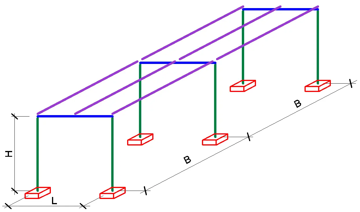
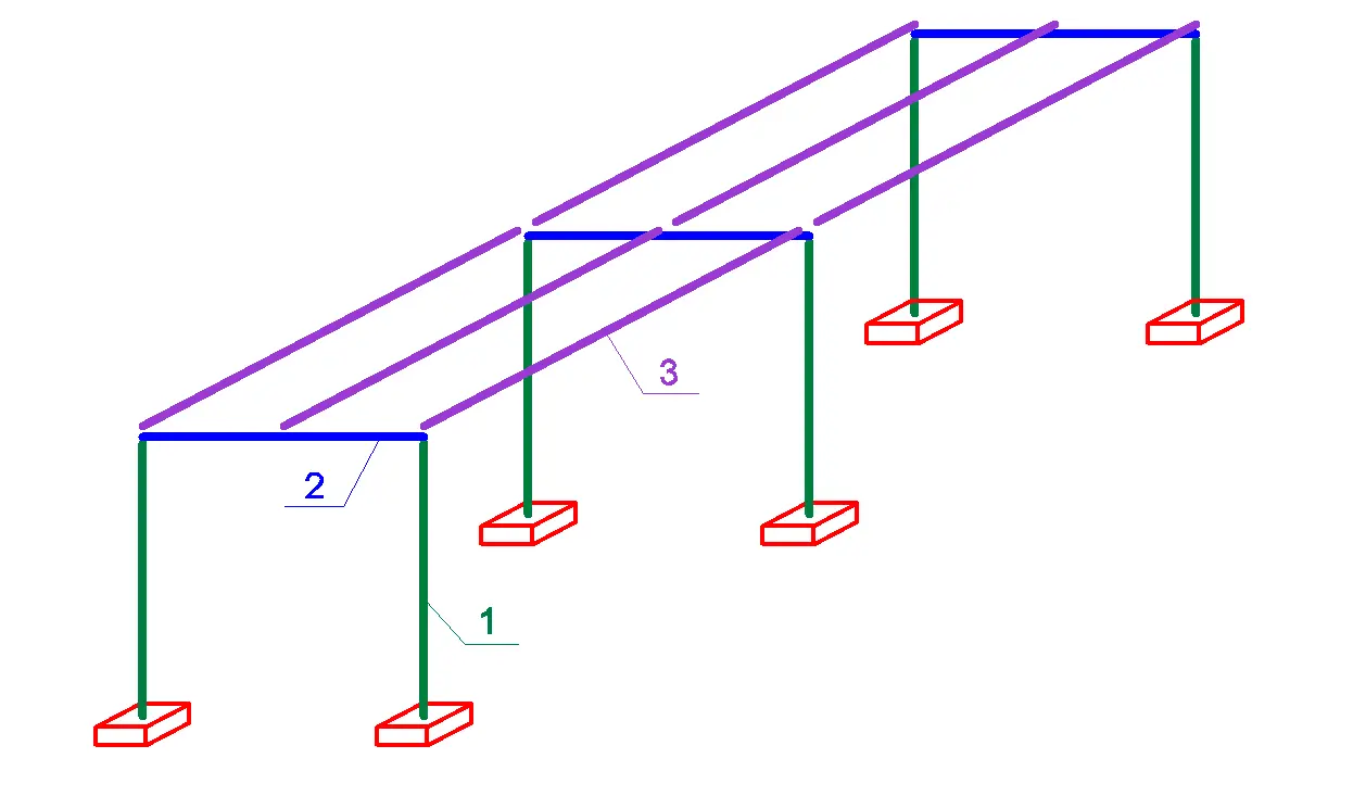
This calculator performs a simplified analysis of a planar metal canopy frame. It evaluates internal forces in the beam and columns, and selects purlin and main member sections for strength, stability, and deflection based on the given geometry and loads.
The calculation is intended for preliminary sizing and comparing options. The model is planar (2D). Actions are considered as vertical loads on the roof area and horizontal wind action on the frame.
Guidelines and recommendations
European references. The calculation logic follows the Eurocodes approach. Load combinations and limit states. EN 1990. Actions. EN 1991-1-3 (snow) and EN 1991-1-4 (wind). Steel member design and section checks. EN 1993-1-1.
Units and conversions. Linear dimensions are converted to metres. Area loads are treated as actions per 1 m² of roof area. For converting mass to force the calculator uses an engineering approximation g ≈ 10 m/s². In practice this means 1 kg ≈ 10 N, which is convenient for preliminary estimates.
Design factors for ULS. To approximate Eurocode-style ULS, partial factors are applied. For unfavourable permanent actions γG = 1.35. For unfavourable variable actions γQ = 1.50. In the calculator, snow and wind are treated as variable actions with factor 1.50. Combination factors ψ for accompanying actions are not applied, so the result is usually conservative, especially when both snow and wind are set to significant values.
Purlin model. Purlins are analysed as simply supported beams under uniformly distributed load. The purlin span equals the canopy width B. The purlin spacing along the length is defined by the number of bays n. Lprog = L / n. The design line load transferred to one purlin is formed from snow and permanent area loads. Nprog = (qs·1.50 + g·1.35) · Lprog · B. This value is then converted into a uniform load w over the purlin span, and the maximum bending moment for a uniform load is calculated. Mmax = w · B² / 8.
Purlin selection for bending strength. The required section modulus is obtained from the bending check. Wreq = Mmax / fy. The nearest section with W ≥ Wreq is selected. Here fy comes from the chosen steel grade and W is taken from the section properties list.
Purlin deflection check. Deflection is calculated using the classical simply supported beam formula for uniform load. f = 5 · w · B⁴ / (384 · E · I). The calculator uses E = 200000 MPa. The deflection limit is set as flim = B / nlim, where nlim is chosen by span in a range of about 120-300. The longer the span, the stricter the limit. If f > flim, the section is increased until the check is satisfied.
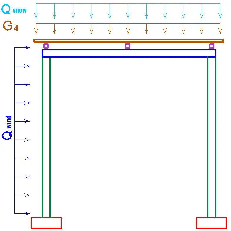
Vertical action on the frame. The design vertical force on the roof area is formed from snow and permanent area loads and the roof area. Q = (qs·1.50 + g·1.35) · B · L. The self-weight of purlins is additionally included via their mass and quantity. The vertical action is then converted into a uniform load along the main beam span. q = Q / L.
Wind action on the frame. Wind area load is converted into horizontal action on the frame through the canopy width and the ULS factor. qw = qwind · B · 1.50. The resulting horizontal force over the frame height is estimated as Qw = qw · H. This action is used to compute column reactions and bending moments in the beam.
Internal forces and governing bending moment. From the vertical uniform load q and the horizontal wind action, the column reactions and bending moments in characteristic sections are determined. For the beam selection, the governing moment is taken as the largest absolute value among the characteristic moments. M = max(M4, M5, M6). The required beam section modulus is then calculated. Wreq = M / fy.
Beam strength check with shear. Combined bending and shear are assessed via an equivalent stress. σ = √((M / W)² + 4 · τ²). The shear stress τ is determined from the shear force and the geometric properties of the section. If σ exceeds the design resistance of the steel, a larger section is selected.
Beam deflection check. Beam deflection is estimated as for a beam under uniform load, including the self-weight of the selected section. f = 5 · (q + m·g) · L⁴ / (384 · E · I). The limit is applied similarly to the purlins. flim = L / nlim, where nlim is chosen by span in a range of about 120-300. If the limit is exceeded, the beam section is increased.
Column stability and eccentric compression. The axial force in a column is taken as the largest absolute value of the reactions. N = max(|Ny1|, |Ny2|). Eccentricity is considered through the eccentricity ratio e = M / N and the relative eccentricity parameter m = e · A / W, where A and W refer to the selected column section.
Slenderness and buckling reduction factor. The radius of gyration is i = √(I / A). The slenderness is λ = l0 / i. The non-dimensional slenderness is λ̄ = λ · √(fy / 206000). The buckling reduction factor χ is selected based on λ̄ and the eccentricity parameter. The stability check is performed as N / (χ · A) ≤ fy / γM with γM = 1.1. If the check is not satisfied, the column section is increased.
Final section selection logic. For each member, the minimum section is first chosen based on the required W. Then checks are applied. Strength. Deflection. For columns, stability as well. The final section is the smallest one that satisfies all checks.
FAQs
Which design factors are used and why?
The calculator applies an approximation of Eurocode ULS. For permanent actions it uses γG = 1.35. For snow and wind as variable actions it uses γQ = 1.50. This improves comparability with ultimate limit state design.
Why can snow and wind together lead to conservative results?
In Eurocodes, a leading action and accompanying actions are typically combined using combination factors ψ. In this calculator, ψ factors are not applied, so snow and wind are effectively combined without reducing the accompanying action. This simplifies the calculation and usually increases conservatism.
How is deflection calculated and what limit is used?
Deflection of purlins and the main beam is calculated using the uniform-load beam formula with E = 200000 MPa. The allowable deflection is set as L/n, where n is selected by span in a range of about 120-300. This approach matches common practice for preliminary serviceability checks.
How is shear considered in the beam selection?
Strength is checked via an equivalent stress combining bending M/W and shear through τ. The resulting expression is σ = √((M / W)² + 4 · τ²). This helps avoid underestimating stress in thin-walled sections when shear is significant.
How is column buckling checked for eccentric compression?
The axial force and eccentricity are determined first. Then slenderness and the reduction factor χ are used. The check is performed as N/(χA) with γM = 1.1. If the check is not satisfied, a larger section is selected automatically.