


About Truss Calculation
The calculator analyses a roof truss as a pin-jointed bar system. Based on the geometry, configuration and applied load, it determines axial forces in the members. It then selects member sizes from the built-in steel and timber section lists, checking strength and stability. The results are presented as a table of forces, reserve, slenderness and an indicative truss mass.
Guidelines and recommendations
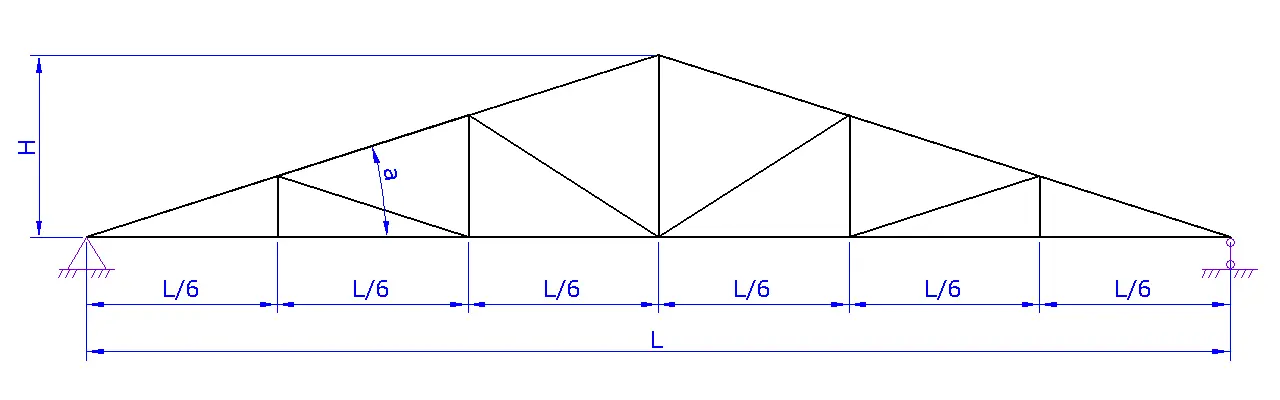
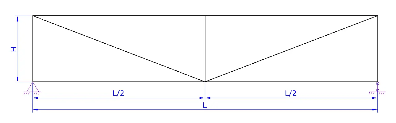
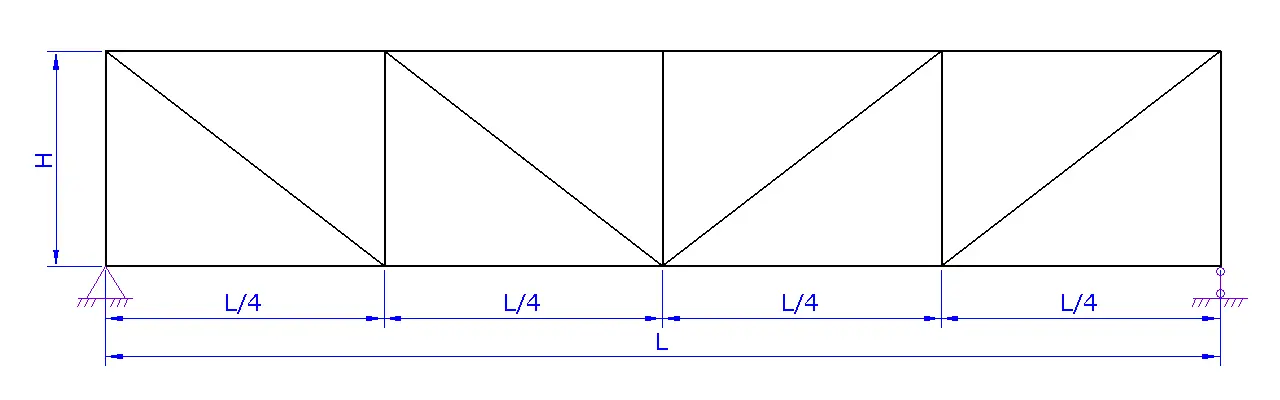
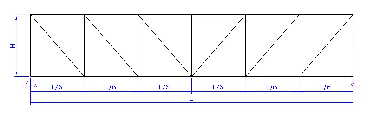
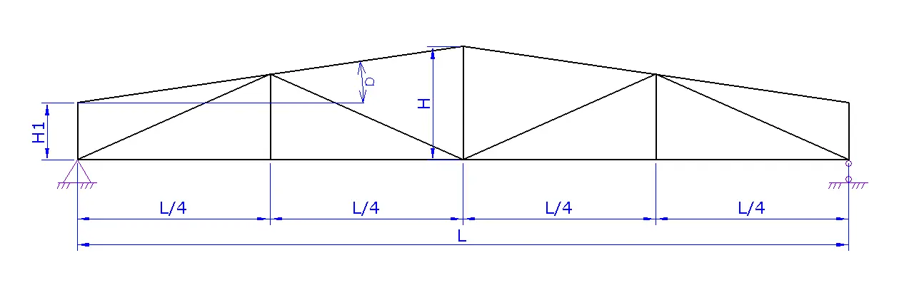
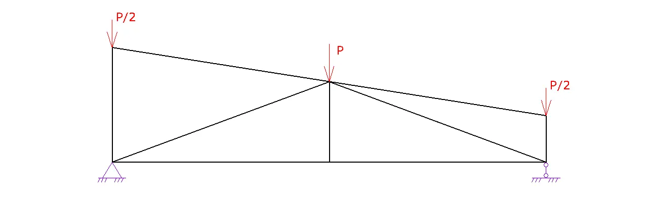
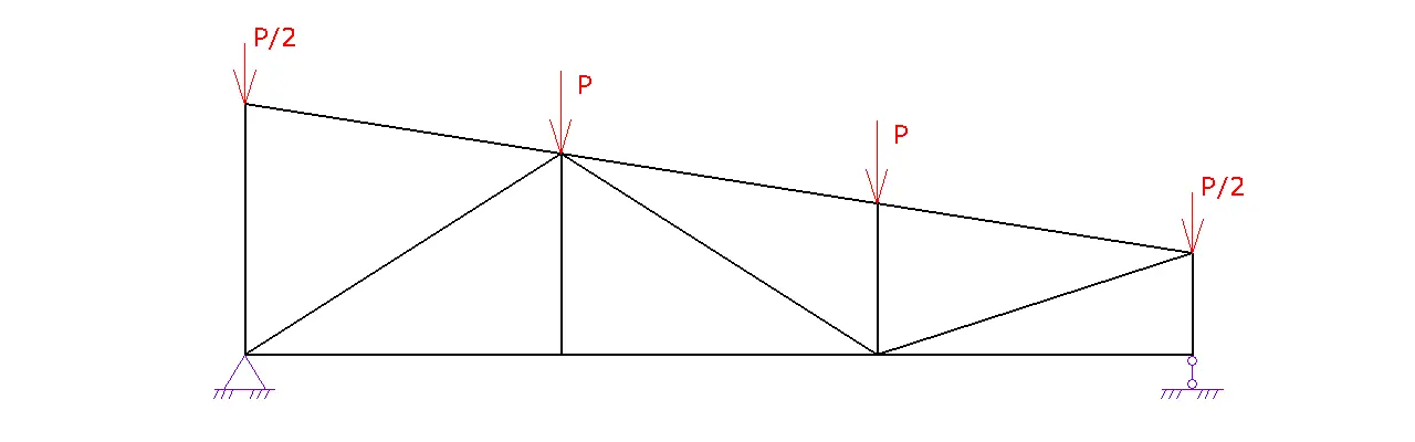
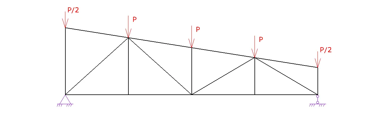
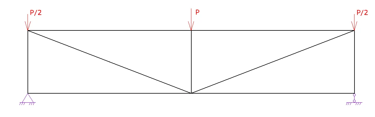
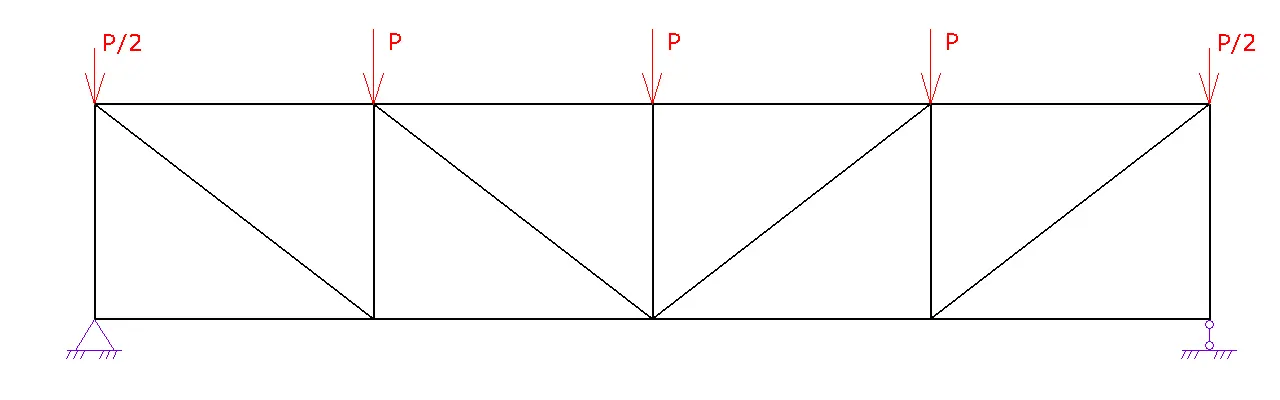
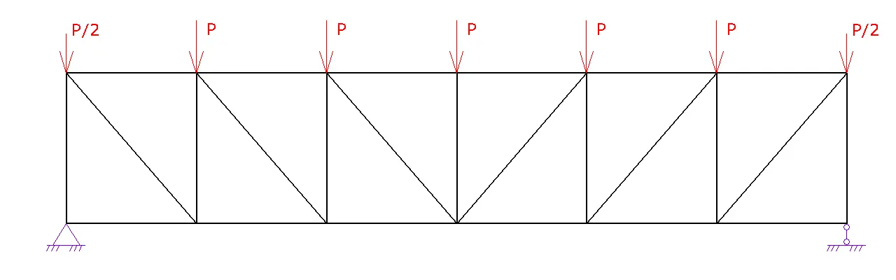
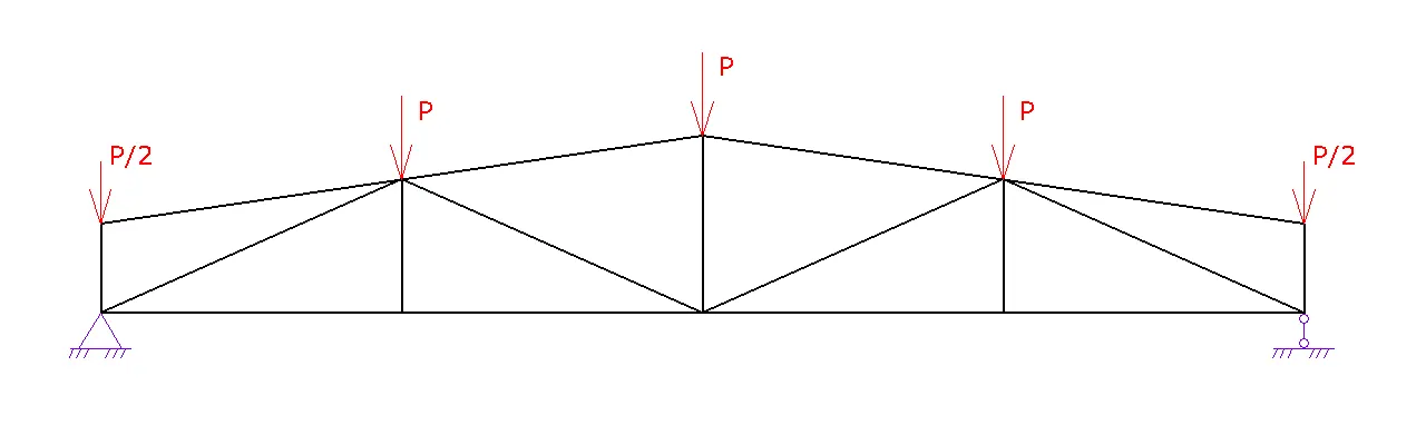
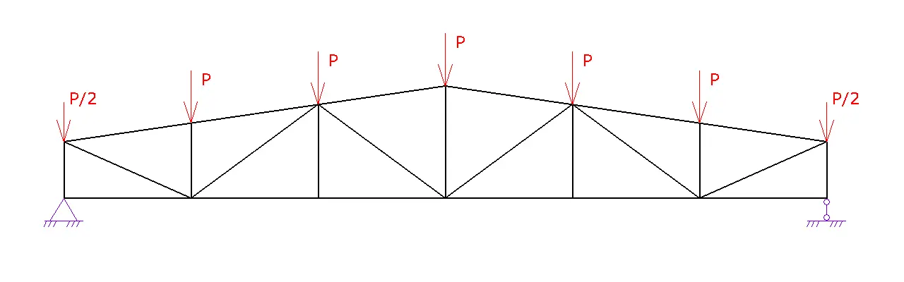
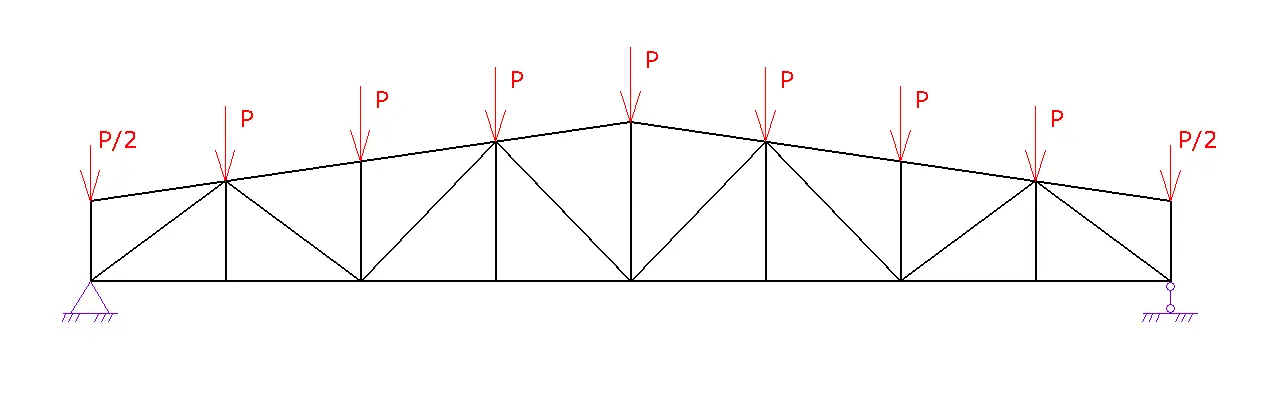
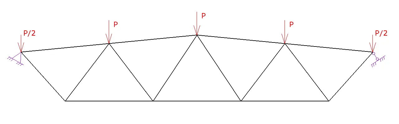
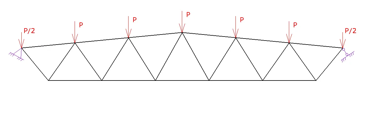
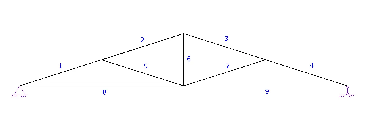
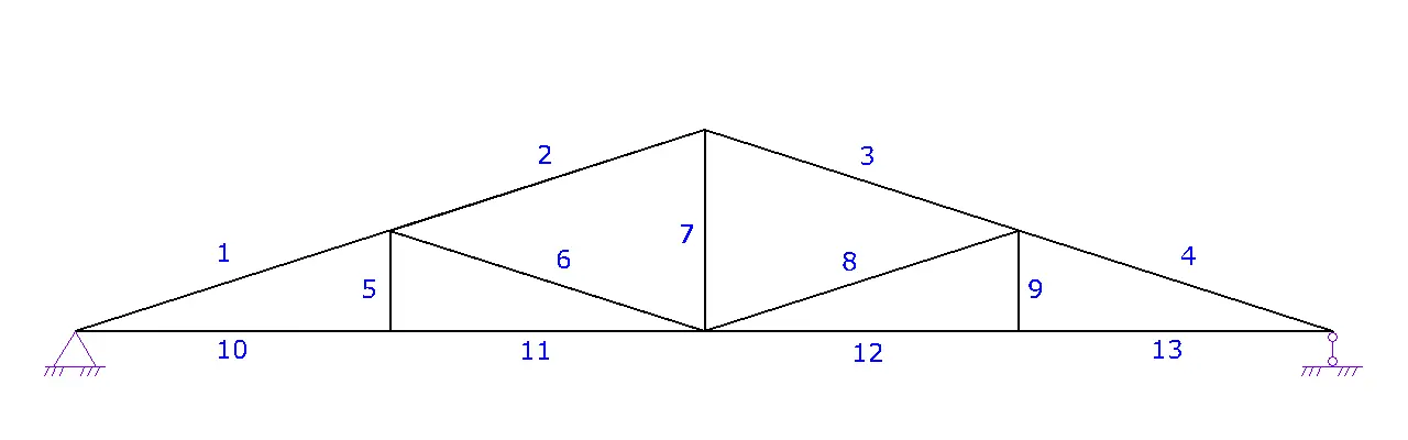
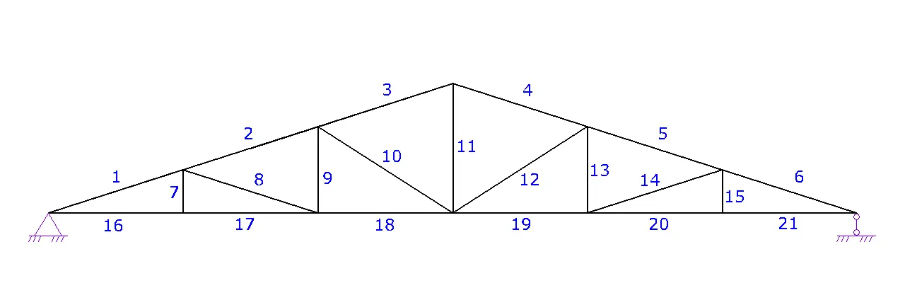
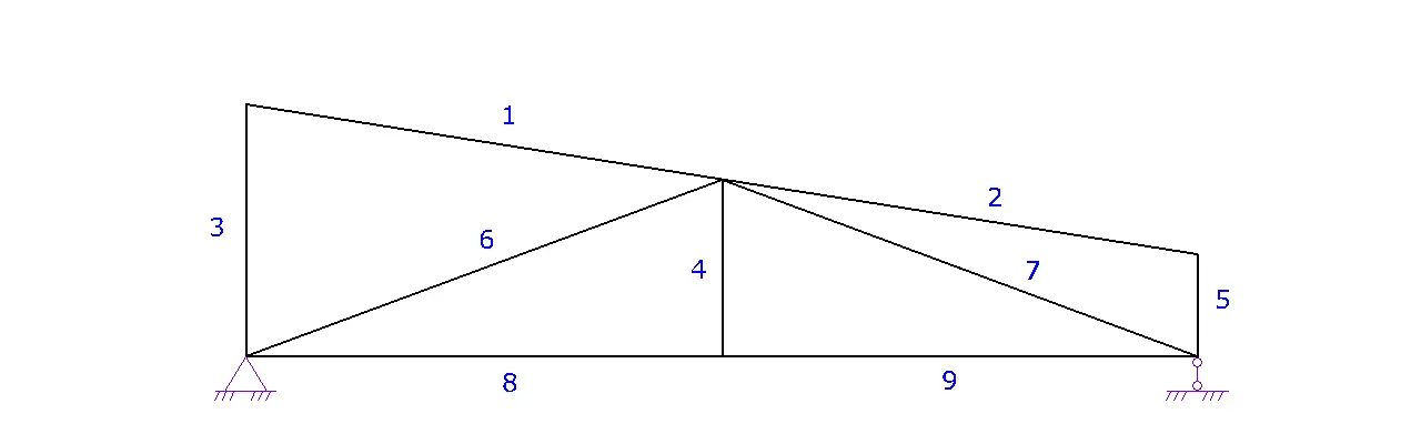
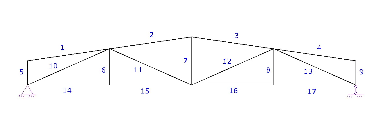
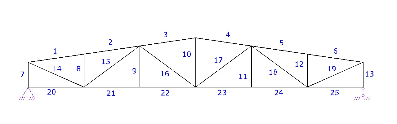
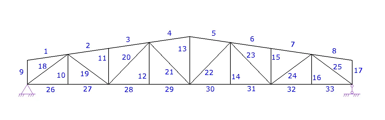
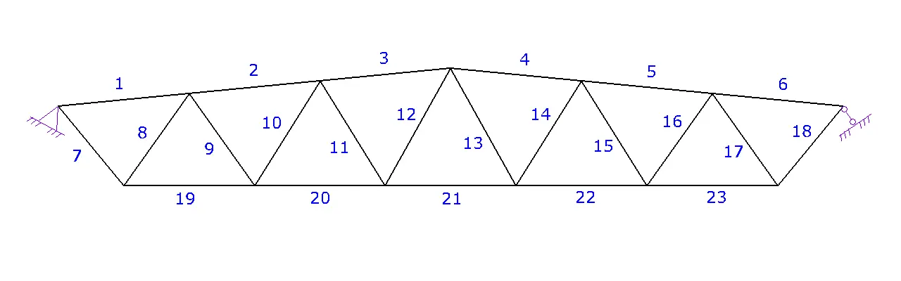
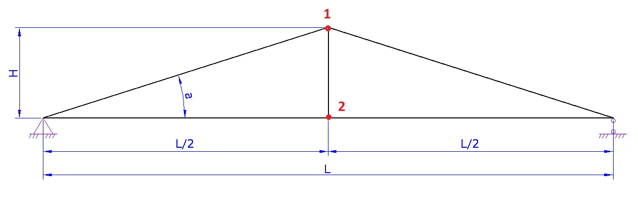
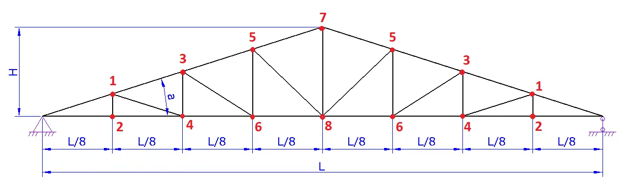
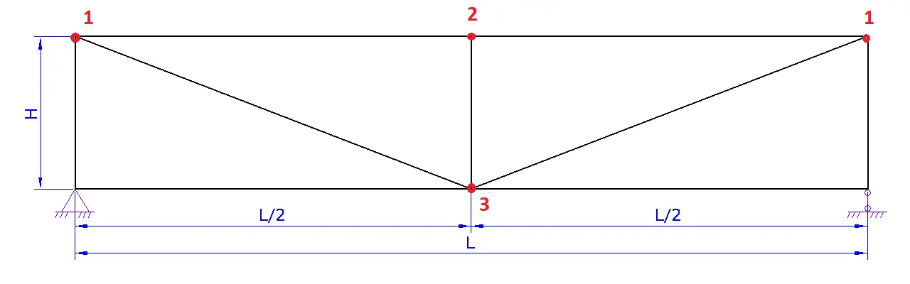
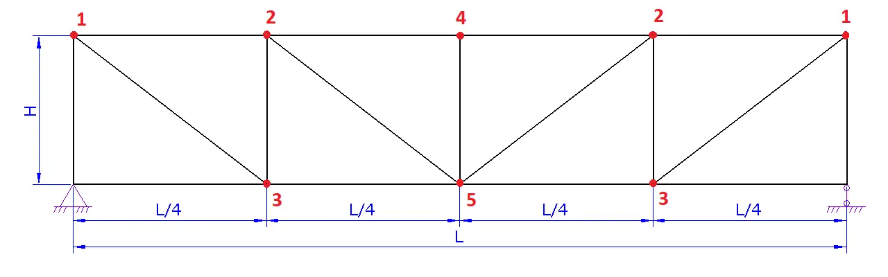
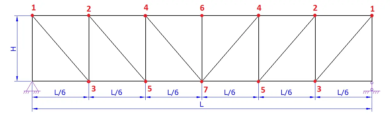
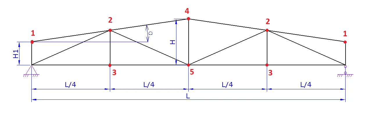
Analysis model. The truss is treated as a system of members connected by pinned joints. Member actions are axial. Member bending and joint rigidity are not included. The load is applied at joints, and any distributed load is first converted into equivalent joint forces.
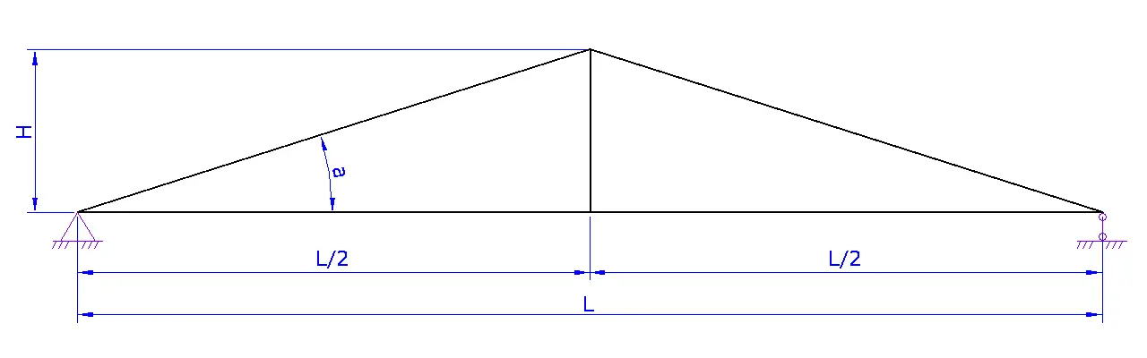
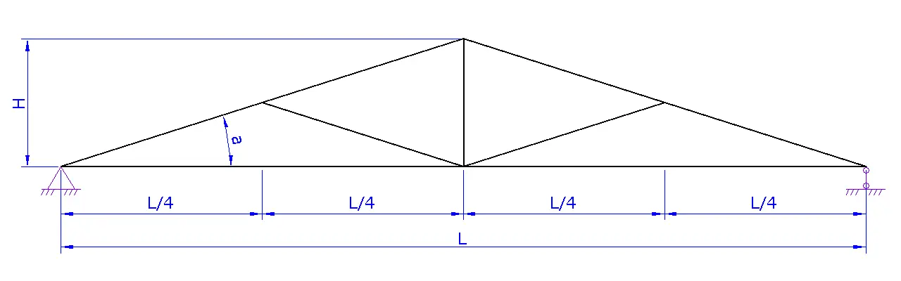
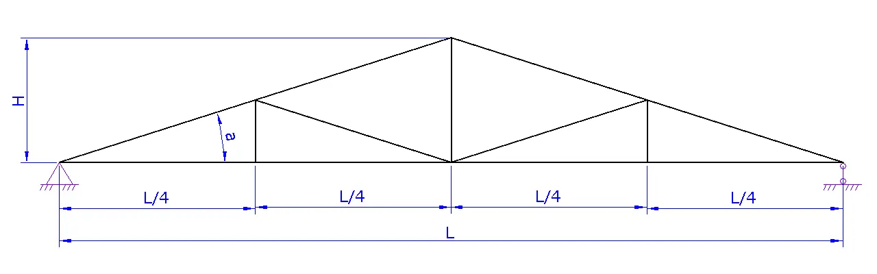
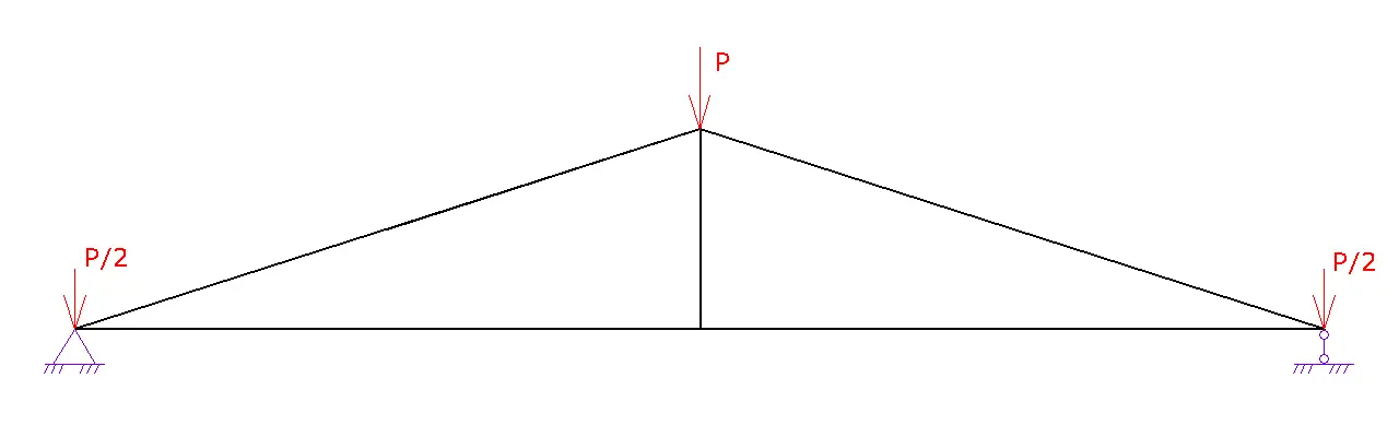
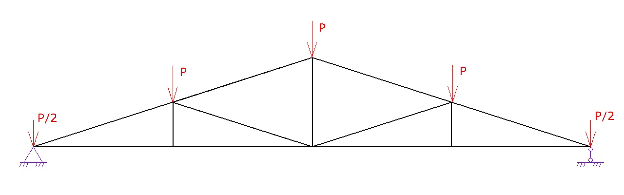
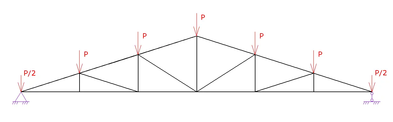
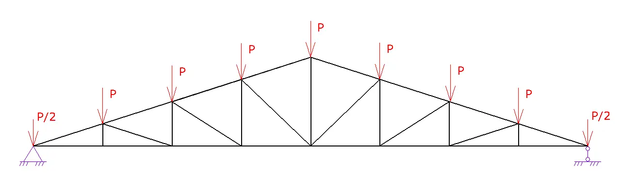
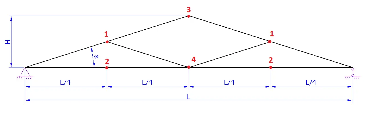
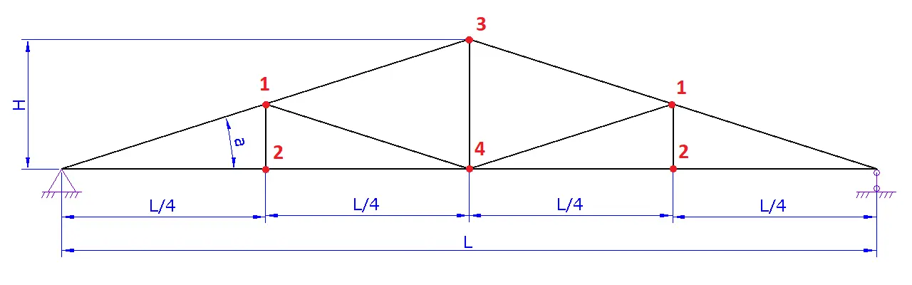
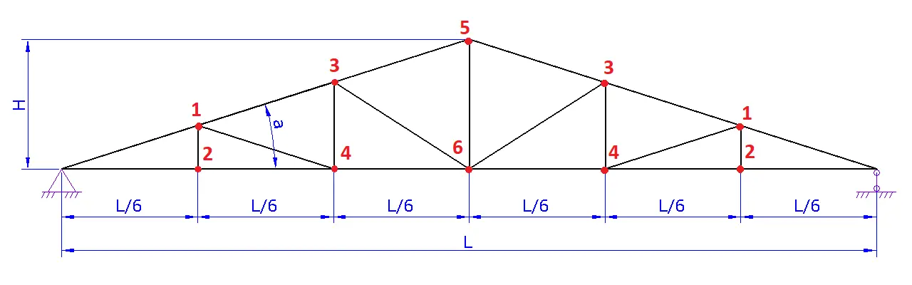
From area load to load per truss. If a roof load q (kN/m² or kg/m²) is specified, the calculator computes the design load for one truss from the area carried by that truss. First, the truss load P is obtained as P = q · L · s, where L is the truss span (m) and s is the truss spacing (m). Then P is distributed to the loaded joints. The number of joint loads depends on the selected truss configuration and the number of panels, so the split P_node = P / n is used, where n is the number of load application points.
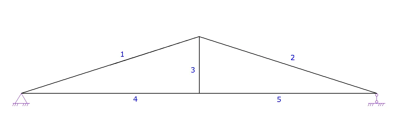
Support reactions and member forces. After the joint loads are defined, support reactions are calculated. Member forces are then obtained using analytical relationships for the selected typical configuration. The result for each member is the axial force N (shown in the table as the force). The sign of the force is used to choose the set of checks. For tension members, a stress check is applied. For compression members, stability is additionally considered through a reduction factor.
Strength check (stresses). For each member and selected section, the design stress is calculated as σ = |N| · 10 / (A · φ). Here A is the cross-sectional area (mm²), φ is a reduction factor for compression members, and the multiplier 10 is an approximate conversion from kgf to N so that stress is obtained in MPa when A is in mm². For tension, φ = 1 is used. The resulting σ is compared with the design resistance of the material corresponding to the selected steel grade or timber type.
Buckling (slenderness) of compression members. Slenderness is evaluated in the truss plane and out of plane. The section radii of gyration i and iy are used together with effective lengths Leff and Ly,eff. Slenderness values are computed as λ = L_eff / i and λ_y = L_y,eff / i_y. The governing value is λ_max = max(λ, λ_y). A reduction factor φ is determined from λ_max, reducing the design capacity of the compression member. If slenderness exceeds the limit, the member is flagged as not meeting the stability condition.
Section selection algorithm. For each member, the calculator takes the list of available sections for the chosen section type. Sections are checked in ascending order until the first one that passes is found. The final section is the minimum section that satisfies the adopted checks. The table shows the reserve from the governing check and the slenderness values in both directions.
Indicative mass. The truss mass is calculated as the sum of the member masses. For each member, m = A · L · ρ is used, where A is the area (m²), L is the member length (m) and ρ is the material density. Typical density values are used. For steel, 7850 kg/m³ is used. For timber, 500 kg/m³ is used.
Relation to European standards. The adopted calculation sequence follows the general approach for trusses as bar systems and uses methods applied in Eurocode practice. For actions and combinations, EN 1990 and EN 1991 are the main references. For steel members, EN 1993-1-1 is the reference. For timber members, EN 1995-1-1 is the reference.
Out-of-plane bracing of joints
Purpose of bracing. Bracing limits out-of-plane movement of the truss and reduces the effective buckling length of compression members. In real structures this is typically provided by purlins, bracing between trusses, struts and roof decking elements that restrain joints against lateral displacement.
How it is used in the calculation. For out-of-plane stability, a separate slenderness is evaluated, based on the out-of-plane effective length and the radius of gyration about the weak axis. In simplified form the relation λ_y = L_y,eff / i_y is used, where L_y,eff is defined by bracing and i_y is taken from the selected section. A smaller L_y,eff means lower out-of-plane slenderness and higher stability.
Mark braced joints. In this mode the out-of-plane effective length is defined by the marked joints. A joint marked as braced is treated as a lateral restraint point. For the top chord and bottom chord, the maximum segment between adjacent restraints is determined. If restraints are sparse, the effective length is taken as the worst unbraced out-of-plane span up to the nearest restraint.
Set bracing spacing. In this mode bracing is defined by a spacing value without referencing specific joints. The spacing for the top chord and bottom chord (mm) is used directly as the out-of-plane effective length L_y,eff for the corresponding chord. This approach is convenient when purlins or bracing are placed regularly.
Practical meaning of the choice. If you know the actual points where purlins or bracing restrain the joints, the joint-marking mode usually gives a more realistic estimate. If bracing is regular, the spacing mode allows you to quickly account for how bracing frequency affects stability. The general approach to stability and bracing aligns with EN 1993-1-1 and EN 1995-1-1.
Typical spacing guidance. In practice, top-chord bracing often follows the purlin or decking spacing. Common values are roughly 1000–2000 mm, but the actual spacing depends on the roof system, bracing layout and spans. Higher compression forces and more slender members typically require closer bracing.
FAQs
Why an area load is converted into a load per truss
The roof covering transfers load to the trusses through the tributary area carried by each truss. Therefore, the area load is multiplied by the span and the truss spacing. The resulting force is then distributed to the joints where loads are applied in the analysis model.
Why member actions are treated as axial, without member bending
Trusses are typically analysed as pin-jointed systems in which members work in tension and compression. In this approach, member bending and joint rigidity are not the primary source of member forces. It is convenient for quick section selection and for comparing geometry options.
What the reserve in the results table means
The reserve indicates how much the selected section exceeds the minimum required by the adopted check. It is derived from the ratio of the material design resistance to the calculated stress, with stability taken into account. A negative reserve means the selected section does not pass the check.
Why slenderness matters for compression members
Compression members can lose stability before the material resistance is reached. Therefore, the calculation uses slenderness in-plane and out-of-plane and takes the more adverse case. A reduction factor is applied based on slenderness, lowering the allowable capacity.
Can the results be used to select a section for purchase
The table shows section dimensions in millimetres and the calculated member forces. This helps to select a close standard section from available products. When substituting a catalogue section, it is important to keep the area and second-moment properties at least as good as those of the selected section.