


About Gutter System Calculation
This calculator performs a simplified bill-of-materials estimate for a roof gutter system based on building geometry. It determines the total length of gutters and downpipes, and gives an approximate quantity of connectors, gutter brackets, outlets and common fittings. The result is intended for preliminary material planning and for comparing layout options before choosing a specific manufacturer system.
Reference values and recommendations
Units and standard lengths
Units. All entered dimensions are converted from centimeters to meters. Notation: building length Ahouse (m), building width Bhouse (m), eaves overhang Seaves (m), building height Hhouse (m).
Eaves line length. For each side that has a gutter, the effective length includes the overhang: Lside=Ahouse+2·Seaves or Lside=Bhouse+2·Seaves.
Lside=Ahouse+2·Seaves
Total gutter length by roof type
Gable roof. Two identical eaves lines are used. Total gutter length: Lgut=2·(Ahouse+2·Seaves).
Mono-pitch roof. One eaves line is used. Total gutter length: Lgut=Ahouse+2·Seaves.
Hip roof. Four eaves lines are used: two along Ahouse and two along Bhouse. Total gutter length: Lgut=2·(Ahouse+2·Seaves)+2·(Bhouse+2·Seaves).
Lgut=ΣLside
Rounding. Length results are shown to 0.1 m (rounded to tenths): 12.34 m → 12.3 m.
Gutter brackets and gutter connectors
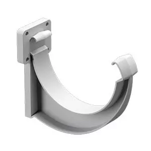
Gutter brackets. For each eaves line, the number of brackets is based on the bracket spacing sgut (m). The count uses the number of intervals and adds one bracket at the end.
Nbr,side=ceil(Lside/sgut)+1
Total bracket quantity. The calculator sums Nbr,side for all sides where a gutter is installed.
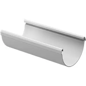
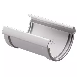
Gutter connectors. If the standard gutter section length is lgut (m), a side needs ceil(Lside/lgut) sections. The number of connectors on that side is one less, but not below zero.
Ncon,side=max(0,ceil(Lside/lgut)-1)
Outlets, downpipes, and downpipe height
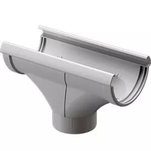
Number of outlets. The number of outlets Nout is entered by the user and directly defines the number of downpipe stacks. All vertical drainage components are calculated from Nout.
Vertical height of one stack. The effective vertical height is taken as Hv=max(0,Hhouse-Seaves) to reflect that the outlet is offset outward by the eaves overhang.
Hv=max(0,Hhouse-Seaves)
Transition from outlet to downpipe. An additional diagonal segment across the overhang is approximated as Seaves·√2. The length of one stack is Lstack=Hv+Seaves·√2. Total downpipe length: Lpipe=Nout·Lstack.
Lpipe=Nout·(Hv+Seaves·√2)
Pipe brackets, couplers, elbows, and outlets at the bottom
Pipe brackets. With pipe bracket spacing spipe (m), brackets for one stack are Nbr,pipe=ceil(Hv/spipe)+1. Total: Nbr,total=Nout·Nbr,pipe.
Nbr,total=Nout·(ceil(Hv/spipe)+1)
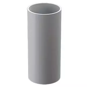
Downpipe couplers. If the standard pipe section length is lpipe (m), one stack needs ceil(Hv/lpipe) sections and therefore max(0,ceil(Hv/lpipe)-1) couplers. The total is multiplied by Nout.
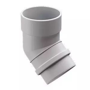
Elbows and bottom discharge. The simplified estimate assumes 2 elbows per stack (top connection) and 1 bottom discharge outlet per stack: Nel=2·Nout, Ndis=Nout.
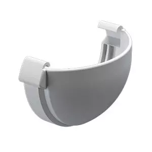
Gutter end caps and corner pieces
Roof layouts without corners. For gable and mono-pitch layouts, end caps are provided: 4 pcs for two gutter lines and 2 pcs for one gutter line. This corresponds to two ends on each eaves line.
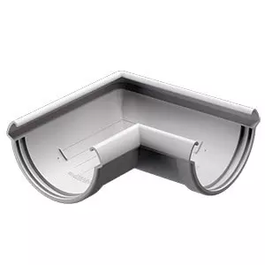
Hip roof layout. The estimate uses 4 external 90° corners (one per building corner). End caps are not listed as a separate item.
Special case for end caps. For the hip roof layout, more end caps may be needed when the outlet count Nout>3. In this simplified approach, a practical reference is used: 4 pcs for Nout≤3 and 8 pcs for Nout>3, representing a layout with additional breaks in the gutter runs.
Standards reference
Related European standards. For roof rainwater drainage principles and typical layouts, EN 12056-3 (Gravity drainage systems inside buildings, Part 3 - Roof drainage) is commonly referenced. For gutters and hangers, EN 612 (Eaves gutters) and EN 1462 (Gutter brackets and supports) are also used. This calculator applies geometric relationships and user-defined bracket spacing as working assumptions. For final sizing and hydraulic capacity checks, use the requirements of these standards and the manufacturer’s guidance.
FAQs
Why does the calculator not select pipe diameter and gutter size?
This tool estimates quantities from geometry and fastening spacing. Sizing depends on rainfall intensity, catchment area, slopes, and the hydraulic capacity of components. For that, apply roof drainage rules in EN 12056-3 and the catalog data of the chosen system.
Where does the Seaves·√2 addition come from in the pipe length?
It is a simplified estimate of the diagonal segment from the outlet at the eaves line to the vertical downpipe. Real geometry depends on overhang projection and elbow arrangement, but Seaves·√2 provides a stable planning reference for preliminary pipe length.
Why are gutter brackets calculated as ceil(Lside/sgut)+1?
The spacing sgut defines the maximum distance between brackets. The ceil function rounds up so the spacing is not exceeded, and +1 accounts for the end bracket. This is a standard way to obtain a minimum adequate bracket count for a given spacing.
How should I interpret gutter and pipe length in meters if parts are sold in sections?
Lgut and Lpipe show the total required linear meters. Connector quantities are derived from the standard section length lgut or lpipe using ceil(L/l)-1 to estimate the number of joints. For purchasing, section counts are typically rounded up and a 5-10% allowance is added for trimming.
Why are end caps sometimes replaced by 90° corners?
In a hip roof layout the gutter run has external corners, so 90° corner pieces become the primary fittings rather than end caps. In layouts without external corners, gutter runs end at open ends, so end caps are used. Final detailing depends on the chosen routing and outlet locations.